Electronics Lab A Comprehensive Guide
The electronics lab provides a practical and engaging introduction to the fascinating world of electronics. This guide explores the fundamental concepts, essential tools, and safe practices for working in a lab environment. From understanding basic components to troubleshooting complex circuits, we’ll cover all aspects of this crucial field. This comprehensive overview will equip you with the knowledge and skills needed to excel in electronics design and implementation.
The lab environment is crucial for both educational and professional settings. We’ll explore different types of labs, from hobbyist projects to professional setups, highlighting the equipment, safety procedures, and experimental techniques used in each. Specific examples, like building a simple amplifier, will illustrate the hands-on application of theoretical knowledge.
Introduction to Electronics Labs
An electronics lab is a dedicated space equipped with tools and materials for experimentation and learning in the field of electronics. It’s a vital environment for both educational and industrial settings, fostering practical understanding and skill development. These labs allow for hands-on exploration of electronic circuits, components, and systems.
The purpose of electronics labs is multifaceted. In educational settings, they provide students with practical experience to solidify theoretical concepts learned in classrooms. In industry, labs are critical for testing and verifying designs, troubleshooting problems, and developing new electronic products. Their importance lies in their ability to bridge the gap between theory and practice, enabling both learning and innovation.
Typical Equipment in an Electronics Lab
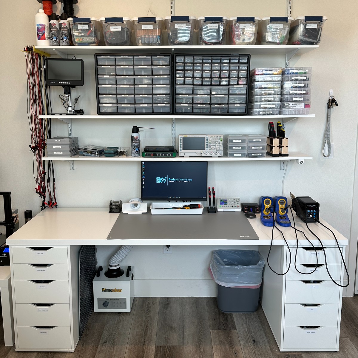
A standard electronics lab is furnished with various tools and instruments essential for experimentation. These include multimeters, oscilloscopes, function generators, breadboards, soldering irons, and various electronic components like resistors, capacitors, inductors, diodes, transistors, and integrated circuits. The specific equipment may vary depending on the lab’s intended use. For instance, an educational lab might have a limited range of components compared to a professional lab.
Safety Procedures in Electronics Labs
Safety is paramount in any electronics lab. Adherence to safety protocols minimizes the risk of electrical shock, burns, or equipment damage. Students and personnel should always follow the established safety guidelines provided by the lab instructor or supervisor. Common safety procedures include wearing appropriate personal protective equipment (PPE), such as safety glasses and gloves. Understanding and following safety protocols is crucial to ensure a safe and productive lab environment.
Comparison of Electronics Lab Types
| Characteristic | Hobbyist Lab | Educational Lab | Professional Lab |
|---|---|---|---|
| Purpose | Personal experimentation, project building, learning new skills | Student training, practical application of concepts, skill development | Research and development, testing and verification, design validation |
| Equipment | Basic multimeters, breadboards, soldering stations, limited component selection | Standard multimeters, oscilloscopes, function generators, wide range of components | Advanced oscilloscopes, spectrum analyzers, signal generators, sophisticated test equipment, wide range of components |
| Space | Home workshop, small dedicated area | Dedicated classroom or lab space | Large, well-equipped lab space with controlled environment |
| Budget | Relatively low | Moderate | High |
| Safety Measures | Basic precautions | Strict adherence to lab safety procedures | Rigorous safety protocols and procedures |
A comparison of different types of electronics labs highlights the varying needs and resources required for each. Hobbyist labs are typically smaller and more personal, while educational labs cater to students’ learning needs, and professional labs are equipped for complex testing and development projects.
Experimentation and Procedures
Electronics labs are vital spaces for the practical application of theoretical concepts. Hands-on experimentation allows students to solidify their understanding and develop crucial problem-solving skills. The procedures and safety protocols employed during these experiments are paramount to ensure a safe and productive learning environment.
Types of Experiments Conducted
Various experiments are conducted in electronics labs, encompassing a broad spectrum of topics. These include but are not limited to circuit analysis, component testing, amplifier design, and digital logic circuit implementation. Different experiments may use various electronic components, tools, and methodologies. Some experiments may require specific setups, specialized equipment, or advanced techniques.
Designing and Conducting an Experiment
A systematic approach is essential when designing and executing experiments. First, the objective of the experiment must be clearly defined, followed by a detailed procedure. This procedure should article the steps involved in experimenting, including the specific materials and equipment required. Next, data should be meticulously recorded and analyzed, drawing conclusions based on the observed results. Finally, the experimental findings should be documented, providing a clear account of the process, observations, and conclusions.
Safety Protocols
Adherence to safety protocols is critical in electronics labs. These protocols include proper handling of electrical components, use of appropriate safety equipment like insulated gloves and eye protection, and maintaining a safe working environment. Students should be mindful of potential hazards, such as high voltage, short circuits, and static electricity, and take precautions to avoid them.
Troubleshooting Common Issues
Troubleshooting is a crucial skill in electronics labs. Common issues may include component malfunctions, circuit errors, and measurement inaccuracies. Students should develop a systematic approach to troubleshooting, identifying the potential causes of the problem, testing hypotheses, and implementing solutions. A systematic approach and a good understanding of the circuit design and components are essential to resolve issues effectively.
Example Experiment: Building a Simple Amplifier
| Materials | Procedures |
|---|---|
| Transistors (e.g., 2N2222), Resistors (various values), Capacitors (various values), Breadboard, Connecting Wires, Power Supply (e.g., 9V battery) | 1. Construct the amplifier circuit on the breadboard according to the circuit diagram. 2. Carefully connect the components, ensuring correct polarity where necessary. 3. Apply power to the circuit and check for any short circuits or incorrect connections. 4. Measure the voltage gain of the amplifier using a multimeter, applying a known input signal. 5. Record the results and analyze the output waveform. |
Methods of Measuring Current and Voltage
The accurate measurement of current and voltage is crucial for analyzing electronic circuits. Various methods are employed to measure these quantities, each with its advantages and limitations. A multimeter, for example, can be used to measure both current and voltage. Specific measuring instruments, such as ammeters and voltmeters, are also employed for more precise measurements in certain situations. Furthermore, the choice of measurement method depends on the specific circuit and the expected values of current and voltage.
| Measurement | Method | Description |
|---|---|---|
| Current | Ammeter (series connection) | Connect the ammeter in series with the component to measure the current flowing through it. |
| Current | Multimeter (series connection) | Use the multimeter’s current measurement function to measure the current. |
| Voltage | Voltmeter (parallel connection) | Connect the voltmeter in parallel with the component to measure the voltage across it. |
| Voltage | Multimeter (voltage measurement function) | Use the multimeter’s voltage measurement function to measure the voltage. |
Tools and Technologies

Source: lab-store.org
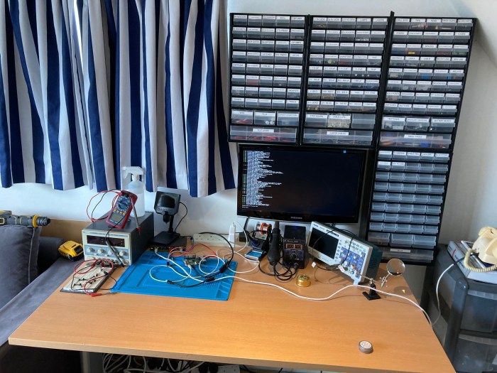
Electronics labs rely heavily on a diverse range of tools and technologies to facilitate experimentation and analysis. Proper utilization of these tools ensures accurate measurements and reliable data collection, ultimately contributing to a deeper understanding of electronic principles. From fundamental components to sophisticated simulation software, this section details essential tools and technologies for conducting experiments.
Essential Tools in Electronics Labs
Essential tools in electronics labs facilitate accurate measurements and experiments. These tools allow for observation of voltage, current, and resistance, crucial for troubleshooting and circuit design.
- Multimeters: Multimeters are versatile instruments used to measure various electrical parameters, including voltage, current, and resistance. Different types of multimeters cater to diverse needs, from basic measurements to more complex analyses. A crucial feature of a multimeter is its ability to measure AC and DC values.
- Oscilloscopes: Oscilloscopes provide a visual representation of voltage waveforms over time. This allows for a detailed analysis of signal characteristics, such as amplitude, frequency, and phase. Understanding signal behavior is essential in many electronic applications.
- Soldering Irons: Soldering irons are indispensable for joining electrical components together. Appropriate temperature control is vital for creating reliable and stable connections. The selection of the soldering iron should consider the type of soldering and the material being joined.
Electronic Components
Understanding the function and operation of electronic components is crucial for designing and analyzing circuits. Familiarizing yourself with these components allows you to build and troubleshoot circuits effectively.
- Resistors: Resistors control the flow of current in a circuit. Their resistance is measured in ohms (Ω). Resistors are fundamental components used in circuits to limit current flow, voltage division, and signal attenuation.
- Capacitors: Capacitors store electrical energy. They are characterized by their capacitance, measured in farads (F). Capacitors are essential for filtering, timing, and energy storage in electronic circuits.
- Transistors: Transistors act as switches or amplifiers in circuits. Their function is based on controlling current flow using a small input signal. Transistors are fundamental in modern electronics for their ability to amplify or switch signals.
Circuit Simulation Software
Software tools enable the simulation and analysis of electronic circuits before physical construction. This approach allows for error detection and refinement before hardware implementation, saving time and resources.
- Functionality: Software packages offer tools to simulate various electronic components and circuits, often including visualization tools for analyzing waveforms and output parameters.
- Advantages: Simulations offer flexibility to experiment with different designs without incurring the cost and time associated with physical prototyping. Simulations allow for precise control of variables, offering a more controlled environment for circuit analysis.
- Disadvantages: Simulations might not always accurately reflect real-world performance due to factors like component tolerances and environmental influences. Software tools might have limitations in their ability to handle very complex circuits.
Comparison of Simulation Software
Different software packages cater to various needs and complexity levels. Choosing the right software depends on the specific requirements of the project.
| Software | Advantages | Disadvantages |
|---|---|---|
| LTspice | Free, easy-to-use, comprehensive component library. | Limited advanced features compared to commercial options. |
| Multisim | Intuitive interface, good for beginners, strong support for industry-standard components. | Subscription-based might not be as cost-effective for individual use. |
| Proteus | Wide range of components, versatile simulation capabilities, excellent for PCB design. | Can be more complex to learn, potentially higher cost. |
Multimeter Specifications and Uses
Multimeters are essential for measuring electrical parameters in electronic circuits. Different types cater to various needs.
| Type | Specifications | Uses |
|---|---|---|
| Analog Multimeter | Uses a needle display. | Simple measurements, good for basic tasks. |
| Digital Multimeter | Displays readings numerically. | More precise measurements, widely used in various applications. |
| Clamp Meter | Measures current without breaking the circuit. | Measuring high currents, assessing faults in power lines. |
Project Design and Implementation
Source: me.uk
Designing and building electronic projects involves a systematic approach, starting from conceptualization to final implementation and testing. This process requires careful planning, adherence to established procedures, and a keen understanding of the underlying principles. A successful project is built upon a strong foundation of design, thorough testing, and meticulous documentation.
Steps in Designing an Electronic Project
A structured approach is crucial for successful project completion. This involves a series of steps, each contributing to the final product. First, a clear understanding of the project’s goals and objectives is essential. Then, a detailed design plan is developed, outlining the necessary components, connections, and functionalities. Thorough research and prototyping are essential to verify the design’s feasibility. Building the circuit and testing its functionality are subsequent stages, followed by refining and adjusting the design based on the results. Finally, documentation is vital for future reference and collaboration.
Examples of Electronic Projects
Numerous electronic projects showcase the diverse applications of electronics. A simple radio circuit, for instance, demonstrates the principles of signal transmission and reception. It involves tuning circuits, amplification stages, and antennas. Another example is a digital clock, which uses integrated circuits, counters, and displays to keep accurate time. These projects highlight the versatility of electronic components and their applications in various systems.
Importance of Circuit Diagrams and Schematics
Circuit diagrams and schematics are vital for visualizing and understanding the connections between components in an electronic circuit. They provide a standardized representation of the circuit, making it easier to analyze, troubleshoot, and replicate the design. These diagrams use standardized symbols for different components, ensuring clarity and facilitating communication among engineers and technicians. This visual representation is crucial for comprehending the circuit’s operation and identifying potential issues.
Documenting and Presenting Project Findings
Comprehensive documentation is paramount for effectively communicating project findings and conclusions. This involves creating detailed reports that Artikel the project’s objectives, design, implementation, and results. Clear and concise explanations of the design process, including diagrams and photographs, are beneficial. Detailed descriptions of experimental setups, observations, and analyses are crucial. The reports should be presented in a format that is easy to understand and follow, ensuring clarity and precision.
Principles of a Microcontroller-Based System
Microcontroller-based systems utilize a central processing unit (CPU) integrated with memory and input/output (I/O) peripherals. These systems are programmable, allowing users to tailor the functionality to specific needs. The CPU fetches instructions from memory, executes them, and interacts with I/O devices. The microcontroller’s operation relies on programming languages and specific software tools.
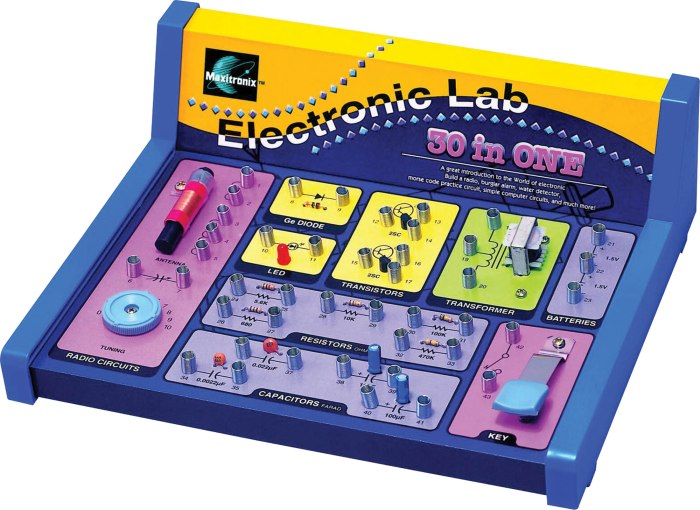
Building a Simple LED Circuit
Understanding the fundamental steps in building a simple LED circuit is essential. This example showcases the basic process for connecting an LED to a power source. The process involves selecting appropriate components, calculating necessary resistances, and creating a circuit diagram.
| Step | Action |
|---|---|
| 1 | Gather components: LED, resistor, battery, and wires. |
| 2 | Calculate resistor value: Use Ohm’s Law (V = IR) to determine the appropriate resistor value to limit current flow through the LED. |
| 3 | Design the circuit: Draw a schematic diagram showing the connections between components. |
| 4 | Connect components: Solder or wire components according to the schematic. |
| 5 | Test the circuit: Verify that the LED illuminates correctly. |
Circuit Analysis and Troubleshooting
Source: com.au
Mastering circuit analysis and troubleshooting is crucial for any electronics engineer. Effective diagnosis and repair of faulty circuits often require a combination of theoretical understanding and practical experience. This section will cover various methods for analyzing circuits, troubleshooting techniques, common faults, and the utilization of circuit analysis software.
Methods for Analyzing Electronic Circuits
Understanding the behavior of electronic circuits is fundamental to troubleshooting. Different methods cater to various circuit complexities and objectives. These include:
- Node Voltage Analysis: This method involves analyzing the voltage at different nodes in the circuit. Using Kirchhoff’s Current Law, the voltage relationships are determined to understand the current flow. This method is particularly useful for complex circuits with multiple interconnected components.
- Mesh Current Analysis: This method involves assigning currents to each loop (mesh) in the circuit. By applying Kirchhoff’s Voltage Law to each loop, the mesh currents are determined, leading to the calculation of voltages across components.
- Thevenin and Norton Equivalent Circuits: These techniques simplify complex circuits by reducing them to a simpler equivalent circuit consisting of a voltage source and a resistance in series (Thevenin) or a current source and a resistance in parallel (Norton). This simplification facilitates the analysis of complex circuits.
- Superposition Theorem: This theorem allows analyzing the effect of each independent source in a circuit individually and then summing up the results to determine the overall response.
Techniques for Troubleshooting Electronic Circuits
Troubleshooting involves systematically identifying and correcting faults in electronic circuits. A systematic approach is crucial for effective diagnosis. Key techniques include:
- Visual Inspection: Examining the circuit for any obvious physical damage, like broken wires, loose connections, or damaged components.
- Measurement of Voltages and Currents: Utilized multimeters to measure voltage and current across components to identify discrepancies compared to expected values.
- Component Testing: Testing individual components to ensure they are functioning correctly, which often involves comparing their characteristics to the expected values. For example, checking the resistance of a resistor or the capacitance of a capacitor.
- Tracing the Circuit Path: Carefully following the signal path through the circuit to identify where the problem originates.
Examples of Common Circuit Faults and Their Solutions
Identifying and addressing circuit issues requires knowledge of common fault types and their corresponding solutions.
| Fault | Cause | Solution |
|---|---|---|
| Open Circuit | Broken wire, disconnected component | Locate and repair the broken wire or reconnect the disconnected component. |
| Short Circuit | Improper connection or damaged component | Identify and repair the short circuit, often involving replacing the faulty component. |
| Incorrect Component Value | Wrong resistor, capacitor, or other component | Replace the component with the correct value. |
| Ground Fault | Unintended connection to ground | Isolate the unintended connection to the ground. |
Using Circuit Analysis Software
Circuit analysis software like LTSpice or Multisim allows for simulating circuits and identifying potential problems before physical construction.
- Simulation Capabilities: These tools can simulate the behavior of a circuit under different conditions, providing valuable insights into the circuit’s response to various inputs. They help predict circuit performance before building and testing.
- Identifying Problems: By simulating the circuit, software can pinpoint potential issues in component values, circuit connections, or design flaws.
Practical Tips for Effective Circuit Diagnosis
Efficient troubleshooting involves a combination of theoretical understanding and practical experience.
- Document Your Work: Keep detailed records of your troubleshooting steps and observations. This is essential for effective debugging.
- Start with the Simplest Possible Test: Begin with a quick visual inspection and simple measurements to narrow down the possibilities.
- Isolate the Problem: Divide and conquer by systematically isolating sections of the circuit to identify the faulty component or area.
Safety and Maintenance
A crucial aspect of any electronics lab is the implementation of robust safety procedures. Proper handling of equipment and components, along with the safe disposal of electronic waste, prevents accidents and protects the environment. Furthermore, maintaining equipment in optimal condition extends its lifespan and ensures accurate results in experiments.
Importance of Safety Precautions, Electronics Lab
Safety precautions are paramount in electronics labs to mitigate potential hazards. Electrical shocks, component damage, and fire risks are all significant concerns. Adhering to established safety procedures minimizes the risk of injury and damage to equipment, ensuring a safe and productive laboratory environment.
Essential Safety Equipment
Implementing appropriate safety measures is vital for a secure lab environment. Essential safety equipment includes safety glasses or goggles, gloves, and a fire extinguisher. These tools protect personnel from electrical hazards, chemical exposure, and fire incidents. Additionally, having a first-aid kit readily available is crucial for addressing minor injuries.
Procedures for Handling Electronic Components and Equipment Safely
The safe handling of electronic components and equipment is critical to prevent damage and accidents. Always handle components with care, using appropriate tools and techniques. When working with high-voltage components, use insulated tools and ensure proper grounding procedures are followed. Do not force connections, and verify component specifications before use. Follow established protocols for handling and storing components to maintain their integrity.
Proper Disposal of Electronic Waste
The proper disposal of electronic waste (e-waste) is essential for environmental protection. Electronic components often contain hazardous materials. Incorrect disposal can lead to soil and water contamination. Recycling programs and designated collection points for e-waste are available for safe and environmentally responsible disposal. Contact local authorities or recycling centers for information on e-waste disposal procedures.
Best Practices for Maintaining Electronics Lab Equipment
Maintaining electronics lab equipment in optimal condition is essential for reliable operation and accurate results. Regular cleaning and inspection of equipment, including power supplies, oscilloscopes, and multimeters, are crucial. Keeping equipment free of dust and debris and ensuring proper connections and grounding will extend the equipment’s lifespan and prevent unexpected malfunctions. Refer to the manufacturer’s guidelines for specific maintenance instructions.
Important Safety Rules for the Electronics Lab
| Rule | Description |
|---|---|
| Wear appropriate personal protective equipment (PPE). | Always wear safety glasses, gloves, and other PPE as required. |
| Follow established procedures for handling high-voltage equipment. | Use insulated tools and maintain proper grounding procedures. |
| Never work alone with high-voltage or potentially hazardous equipment. | Always have a designated supervisor or colleague present to assist. |
| Kept the lab area clean and organized. | Avoid clutter that could impede safe movement or cause accidents. |
| Report any safety hazard or incident immediately. | Inform the supervisor or designated personnel of any unsafe condition. |
| Properly dispose of electronic waste. | Use designated recycling programs or collection points for safe disposal. |
Final Wrap-Up
Source: wordpress.com
In conclusion, this exploration of electronics labs has covered a broad range of topics, from safety and equipment to project design and troubleshooting. By understanding the fundamentals and applying the practical techniques Artikeld, individuals can embark on exciting projects and contribute to the ever-evolving field of electronics. The key takeaway is that a solid foundation in electronics lab practices is essential for success, whether as a hobbyist or a professional.